Saturday 20 April 2019

Banking tank

As well as the signal cabin, the previous post showed my first (almost-) completed loco, a Drummond 0-6-4T "banking tank". This has been my main modelling project for the last few months, and I'm happy with how it has come together. As you can see, it still needs crankpin washers (I can't find the packet which I'm fairly sure I bought years ago from the 2mm shop!), transfers (I've drawn the artwork for these but am waiting for them to be produced), vacuum pipes, and tablet capture apparatus on the cab sides.


Below is a view of the chassis as it stands - the next step here is to fit a decoder, which will probably go in the coal bunker. Running is not bad, and hopefully will improve with running in a bit more. I've weighed the body down with some chunks of lead in the side tanks and the front of the boiler, but it looks like I might need a bit of weight at the rear end too - I'm not sure.


The motor is an Association flat can, driving through a 30:1 worm and a 14:25 reduction with M0.3 spur gears to the central driving axle.


This exploded view shows the chassis in bits, prior to painting. As well as the coupling rods, I etched templates for the sideframes along with the body, and these templates were used to help cut the frames by hand out of thicker (18 thou, I think) nickel-silver. They are joined with PCB spacer strip from the Association shop. I milled a box for the worm gear out of a chunk of brass, and this screws on to one of the frames to allow for a bit of adjustment. A 12BA bolt at either end of the chassis screws up into a nut soldered in the body.


The bogie was made in a similar way, i.e. with the sideframes cut out by hand and a PCB spacer. As you see in this top view, they have a tab that folds up on to the PCB - this is to provide a bearing surface for the spring-cum-pick up that bears down on the bogie from the main chassis. In the centre of the bogie (top and bottom) there is a square brass washer with a hole for the fixing screw. The bogie is free to slide up and down on this screw. In fact, the hole is elongated sideways, in order to give the bogie a bit of sideplay (this is limited as I didn't allow much width in the centre section of the spacer!). The screw itself is just a 12BA bolt with a length of brass tube soldered on. Another length of brass tubing is soldered into a hole through the main chassis (see picture below), and finally a nut soldered on top.


The body itself was made from my own etch, although this didn't include the boiler or any of the various details. The etched cab roof turned out to be too flimsy so I made a new one from 10 thou material. In the photo at the top you can see that this is still loose and might be glued down once I am happy it is running ok and have fitted the decoder etc. The boiler furniture represent my first attempt at turning these items on the lathe, and I was pleasantly surprised with how straightforward these were (although they are not 100% dimensionally accurate!).


Completed signal cabin


Here's a photo of the painted signal cabin on the layout, although I haven't yet bedded it in to the surrounding ground.

Saturday 3 November 2018

Signal cabin

Currently I'm working on the signal cabin for Corrieshalloch. This is the last major building planned for the layout. There would have been one of these at each end of the station, controlling each end of the crossing loop, but my layout only features one end of the station.

The cabin is based on drawings of one of the two cabins at Garve, albeit in mirror image. Here are a couple of photos of the present state of construction:


In building the model, I was strongly influenced by Jim Watt's recent build of a Caledonian Railway cabin, the construction of which he described in the October 2mm Magazine. I followed Jim's cunning strategy of making an etched jig for soldering up the steps (albeit on a smaller scale!), and I drew these up on an etch along with the windows, doors and barge-boards with their finials. I decided it would be quicker to model the rest in plasticard than to spend time drawing it on the computer.

The windows are more complicated than they look, with up to 6 layers of 10-thou etch in places, to accommodate the panes of "glass" which will be slotted in after painting. To allow this, the windows are all still removable, and indeed some of them are not present in the photo. There's also a rather vulnerable handrail still to be added - I will probably do this after painting along with the downpipes. To facilitate removing the windows, the whole construction is in three pieces, as you see in the next photo:


Putting this lot together out of Evergreen styrene sheet has kept me busy for a while, but it is very nearly at the painting stage now. The roof was made last night from home-corrugated aluminium, in my usual way. It still needs finishing along the ridge.

Wednesday 12 September 2018

Progress update

Although it has been a year since I posted on this blog, I have made gradual progress with the layout during that time. While the layout was on show at the Darlington exhibition last week, I used the opportunity to take some photos. As the scenery progresses, it is starting to look more anachronistic when operating my 1970s stock!

The station area. As you can see, the station building is now painted and glazed, although it still awaits some final details like posters etc. The windows are made of clear styrene with glazing bars scribed and painted on. I'm quite proud of the lamp which was made up from brass and nickel silver, and glazed with Microsol Krystal Clear.
View of the station from the goods yard. The Farish Mark 1 RMB is the latest addition to my 1970s fleet. It is also significant as it is the first time I have turned down the wheels myself (on my Sherline lathe). This was much easier than expected, thanks to a tutorial from Edward Sissling at a NEAG meeting earlier this year. Basically, you just thin down the  back of the flange, and then take as much as you can get away with off the front of the tyre. I didn't have a collet large enough to hold the tyres, so I had to use the chuck, but I followed Edward's tip to use a piece of small-diameter brass tube in the tailstock to hold the other end of the axle. The coach is yet to receive a weathering treatment to blend it in with the rest of the stock.
A closer view of the cattle dock, which is a straightforward build from microstrip. I also had a go at building a raised section of platform for loading the iconic double-decker sheep wagons. At some point, I will work out how to mass produce sheep; current thinking is to use an etched skeleton but if anyone can suggest an affordable source of ready-made animals that might be simpler.
At the other end of the scene, I've made some progress with trees, although there are more to do. All are made of twisted wire (of varying fineness), with Woodland Scenics polyfibre teased out and stuck on with Spraymount. The leaves are the excellent scatter material from Treemendus.
This close-up of the river shows the water that is made from artist's acrylic gloss medium, poured on fairly thick. This was a bit hairy as it is right on the edge of the board, but it is viscous enough that it didn't spill over. The final effect is similar to PVA glue but a bit more transparent. I didn't try to form too many "waves" but rather left it mostly how it landed.
The railway workers' cottages have also reached the painted stage. In fact, since the photo was taken I've begun work on the doors and windows. These I always find tedious and have to be in the right frame of mind.
An overall view taken at the exhibition.
As always, there are many jobs still to be done. As well as finishing the cottages, I've just received an etch from PPD that includes platform fencing and the signal box windows, so those will probably be the next tasks, along with the signal. Highland Railway locomotives and stock are an ongoing project (if "going" is the right word), despite the fact that a number of visitors at Darlington expressed support for the blue-diesel era!

Monday 25 September 2017

Station building

In recent weeks (months?) I've been working on the station building for Corrieshalloch. The styrene shell was covered in a layer of Fimo air drying clay (similar to DAS), glued on with PVA. Once dry, I carved the stonework courses using a needle held in a pin vice. The clock face (between the bottom left windows) is made from a short length of brass tube set in the wall and filled with filler.


The roof is a separate, removable unit. It has a basic structure of styrene with slates made from strips of paper, as for the goods shed. Slating was a little tedious owing to the three dormer windows and many angled cuts required. Microstrip was used to create the guttering and fascia boards around the outside. The chimneys are covered in clay like the main walls of the building.


The chimney pots are quite exciting (for me) as they are turned brass, and are the first items that I've made on my lathe (a Sherline). I was pleasantly surprised with how easy this was. I had to grind a left-handed turning tool (from 1/8" HSS bar), as the lathe only came with a right-handed tool and I needed to get into both sides of the bits that stick out (technical term?). I wasn't sure whether I could do this grinding operation on my little LIDL bench grinder, but it worked a treat. It actually took me a few months to work up the confidence to try making something on the lathe, but I needn't have worried and I'm looking forward to finding uses for it in future. It was quite fun trying to puzzle out the best order in which to make the cuts (the chimneys also have integral spigots for fitting in the roof). I don't have a parting tool so simply cut them off with a piercing saw. I think the results are at least better than the white-metal castings that I have in the drawer (and used for the goods shed).


Tuesday 6 June 2017

Goods shed progress

The goods shed was actually the first structure that I started, a few years back now. I recently decided to progress it further, which basically meant adding the roof, doors and windows. It is entirely modelled in styrene, except for the paper strip roof tiles (printed by computer), the brick paper covering the chimney (from the http://scalescenes.com free demo kit), and the chimney pot (a white metal casting of unknown provenance).

You can see that I've made a start on painting, although there is definitely more weathering to do. I'm going to leave this for the moment and try to blend it into the whole scene at a later stage. Missing also at present are the interior crane and the enamel advertising signs which seemed to grace most of these sheds in photographs of the period. According to Highland Railway Liveries, the shed walls were creosoted, while the doors and windows were painted burnt sienna. I've not found much guidance on how dark or light a shade of burnt sienna was used. so I opted for a reasonably light one as seems to be suggested by the black-and-white photos. Perhaps someone will correct me.

Another couple of problems to be fixed are (1) the gap around the bottom of the building, and (2) the lack of lighting on its front face. I cheated for these photos and used an extra lamp pointed at the layout, but in the long run I think I will need to add another strip of LEDs right at the bottom of the layout fascia.

Also in the top photo are some trees - I made a start on these a while back and need to make many more. They use traditional twisted copper wire, covered in solder. The foliage is represented by various products held on teased out Woodland Scenics poly fibre.

Evident also are the spaces where the station building and waiting shelter will go - these are on my to-do list!

Tuesday 21 March 2017

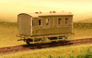
4-wheel passenger brake van

This is the first major item put together from my recent etch. It is modelled on Highland Railway passenger brake van No. 5, as preserved at the SRPS in Bo'ness, and drawn on p.101 of Peter Tatlow's book. Pete Armstrong has also modelled this van in 7mm scale, in his case from the Lochgorm Models kit (see his blog here).

Still missing are vacuum pipes and handwheels, which I will add after painting because I need to make sure that I don't foul the couplings. Glazing will be added simply by slotting into the sides. The white bits are Milliput that I used to fill in some gaps where the parts join together.

Like my previous attempt at a Jones 6-wheel coach, the sides fold up from several layers. This time, I included fold-out footsteps on the inner layer of the end, which fit through slots in the outer layer. I'm very pleased with how it has turned out. The only errors were that I forgot quite a lot of the handrail holes on the inner-most layers. These were easily drilled out, however. Also, I included the handrails on the etch, but these proved too fragile and I replaced them with 0.3mm nickel silver wire.

The photo below shows that there are three main pieces. A 12BA nut is soldered on the inside of the floor (see bottom photo), and this will be used to screw on the chassis. Notice the etched tab on the chassis that locates through a corresponding slot in the floor of the body, to make sure that the two mate together squarely. I'm also showing you the roof here. Following problems trying to bend the full 10 thou thickness for my previous coach, I half-etched much of the material away, just leaving a strip around the edge and a series of longitudinal ribs. This made it much easier to get the curve parallel along the length of the roof, and bending was quite straightforward. I've modelled the lamp-holders in "day time" condition, i.e. no lamps. The covers (and the holes into which the covers fit when lamps are fitted) are made from lengths of brass tube. This was a bit labour intensive so I would quite like to find a quicker method in future.


How exactly I will attach the roof remains to be seen - you can see that it locates on a tab sticking up from the interior spacer. I should probably have included one at the other end. I might even solder in a 12BA nut and use the same fixing screw to attach it, but I don't know whether this will hold the roof down sufficiently around the edges. I may need to glue it. It can't be fixed until after painting because the glazing needs to slot down from the top of the sides - you can just about see the slots in the photo below.