Saturday 28 November 2009

The Warehouse

An interesting building on Inverneuk is a low-relief version of this warehouse at Tain:
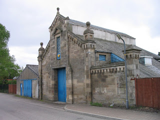
I took this photo while passing through on a (road) trip up North in June 2008. A couple of older views may be found at http://rniescottishailwayrchive.fotopic.net/p25206879.html. In particular, I have included the hoist on the front of the building that is no longer present, and have omitted the burglar alarm.

I began by preparing an approximate scale drawing (on the computer, based on the photos). This was printed out and mounted on cardboard as a mock-up, as featured in this shot of the embryonic scenery:
Construction of the basic superstructure was in styrene sheet. The stonework was laboriously embossed in cartridge paper which was then glued over the plastic shell. The ornamental tops to the walls, including the round finials, were scuplted from Milliput. The triangular sections were formed by running along a plastic scraper with a cut-out of the desired cross-section, although this required just the right "wetness" of the Milliput. The hoist was knocked up from scrap brass strip and bullhead rail.
Unfortunately this building (like the goods shed) is too tall to fit in the box file, so I made the upper section removable:
Here is the finished building in place, painted in acrylics. The surrounding scenery still needs development.

Monday 14 September 2009

08 Update

I've made some progress: constructing the outside frames and, most recently, fitting the coupling rods. The trickiest part was soldering the cranks squarely to the extended axles. When quartering I had to make more adjustments to deal with crankpins that weren't parallel to the axles than I did to get the angles of each wheel right.

I'm still not totally convinced that the chassis rolls down the tilted test track as smoothly with coupling rods as without, but it's close. I still need to attach the motor and see how it runs. Luckily the wheels are just held in the muffs by friction so are still adjustable. I haven't decided yet whether to glue them or not, but if I opt for glueing I want to check more carefully with a back-to-back gauge first (which I need to obtain...).

Saturday 13 June 2009

BR Blue CCT

I've been working on the Chris Higgs BR CCT. Here is a quick preview of the model with base coat of paint, showing the home-produced transfers. Weathering, glazing, and handrail details are still to be done.

Monday 25 May 2009

08 Shunter Progress

In the last month or so I've begun construction of the 2mm Scale Association kit for the BR Class 08 shunter. I've found Graham Ross' blog about the construction of this kit very helpful.

Here is an early view of the frames, with bearings and PCB spacers attached. You can also make out the phosphor-bronze springs, following the method of Mick Simpson. The frames have half-etched holes intended for these. As recommended, the springs came from straightening out Farish N-gauge coupling springs. With this method you also have to shorten the muffs on the axles, which I did by a combination of stanley knife and filing.

This view was taken this morning, showing the chassis with all wheels and gears fitted for the first time. I opened out the muffs on the axles with a 1.5mm drill, so that the wheels are an easy push fit. Hence I will be able to correct the misaligned balance weight on the right-hand wheel! I think when I am happy with the drive I will have to glue the wheels in, by means of the perpendicular hole drilled in the centre of each muff. Unfortunately one of the large balance weights disappeared in between cleaning up and glueing in place, so I had to make a replacement by carefully filing a piece of spare nickel-silver fret.


Finally here is a video of the first "test run" with the motor attached. There is still work to be done in getting it running smoothly. Before this video was taken I found that one of the spur gears was locking, which I seem to have cured by opening out its bearing hole slightly (perhaps it was a result of the axle bearings being opened out to 1.6mm for the springing system?).

Sunday 3 May 2009

Trackwork

As I haven't posted anything about my Inverneuk layout for some time, here is a photo sequence illustrating the method used for trackbuilding.

I used plain rail and PCB sleepers, following closely the excellent instructions in the Beginner's Guide. Building turnouts turned out (sorry) to be much easier than anticipated, having been one of my two main concerns about working in 2mm scale (the other is building working locos, of which more anon). Although I used the standard jig for building plain track, I didn't use a jig for the turnouts, simply building directly on to an Association plan. For simplicity I decided not to design my own tighter turnouts. No chair-plates were used (Inverneuk is a light yard anyway). Two further points. Firstly, I find that running a file along the outsides of the chairs after construction gives a more uniform appearance. Secondly, you can see the gaps filed in the sleepers: these were filled with milliput after construction.

In a departure from more normal practice, the next thing I did was not to fix down the track. Instead I constructed it in several sections, and, while they were still loose, soldered dropper wires to each length of rail. Corresponding holes were drilled in the baseboard. Away from the layout I then sprayed the track sections with primer and brush painted the sleepers and rails with acrylics. However, I'm not convinced acrylics were the best paint for this as they tend to peel off and have had to be re-touched since. The idea of painting the track before fixing follows an article by Bill Blackburn in the 2mm Magazine where he describes how he lays and ballasts the track at the same time.

Here we see a section of track in the process of being layed, alongside a completed section. Pins are prepared to hold it in position, then PVA glue is spread in quite a thick layer underneath, before fixing down the track. At the same time dropper wires are fed through their holes. Then, while the glue is still wet, ballast is sifted into place. I found it advantageous to tamp the ballast at this stage too. After allowing the glue to set the layout was shaken upside down to remove loose grains, and the ballast was touched up where required. At the same time stray grains that had stuck to the sides of the rails were removed.

The choice of ballast material resulted from some experiments. I settled for a mixture of Carr's ash ballast and sand from the local beach. Here is the real thing, on the Kyle line.

And here is the finished track!

P.S. Inverneuk now appears in print (2mm Magazine for April/May 2009).

Sunday 5 April 2009

Brake Van: Painting & Lettering


I've now finished the brake van that I showed at an earlier stage. Again, painting is by artist's acrylics. Glazing was with Microscale "Kristal Klear" (a nice product that very much resembles PVA glue but dries very clear). The large windows - in the ends of the cabin - seem to be about the largest size for which this technique can be applied.

Lettering was the main area of experiment. My initial attempts at a passable interpretation with a paintbrush were unsuccessful, so I opted for waterslide transfers. With no commercial transfers available for this particular vehicle in late 1970's/early 1980's condition, I decided to print my own. I obtained sheets of Expert's Choice white inkjet decal paper (from http://www.bare-metal.com here in the US), and also two Microscale products: "Liquid Decal Film" and "Micro-Sol". The first is painted over the printed decals to seal and waterproof the ink. The instructions suggest spraying this but without an airbrush I opted simply to brush it on. I found that quite a thick coating was necessary to prevent the ink being washed away on subsequent wetting. The "Micro-Sol" liquid is applied to the transfer once in position on the model, thinning the transfer and enabling it to follow contours such as planking. It works very well and is essential with this decal paper, which is rather thick.

To draw the transfers I used the free, open-source vector graphics software Inkscape, which is straightforward to use and very useful for such tasks. I used simple text (with various fonts) and rectangles to copy the markings from a photo (in an old Model Rail magazine). Measurements were taken from the model itself, although I found I had to reduce the size slightly in Inkscape as the drawing was enlarged somewhere along the way to the printer. This is where test printing on cheap paper is very useful!

The greatest problem with computer-printing transfers is that normal printers cannot print white. White text must be done by printing the coloured surroundings on white transfer paper. Matching this surrounding colour to that of the model is tricky. In this case the problem only applied to the lettering on a bauxite/brown background, as the other two transfers are on different coloured patches anyway. I should refer here to the article on using the computer as a modelling tool by Geoff Jones (available to 2mm Association Members on the VAG), as I used the accompanying RGB colour charts to get a rough value for the colour. I printed copies of the transfers with several different background colours and picked the closest. This wasn't a perfect match, and some blending with paint was necessary afterwards.

Here is the computer artwork (three transfers for each side of the van):Here is a photo of some printed transfers (the US penny is about the size of a UK penny!):

Tuesday 17 March 2009

16T Minerals

Here's a picture of my latest wagon, fresh out of the paint shop, though that's not the case with the prototype. Painting is with artist's acrylics, over an undercoat of Tamiya fine grey primer. The wagon is an association chassis and plastic body kit. For some reason I decided to use the kit I had, which didn't have top doors, and add them myself from scraps of styrene. The repairs to the side panels were also from styrene sheet.

So now I have three mineral wagons:
I'm not quite sure whether this wagon should have a darker chassis, or the earlier two should be lighter, or both? I did work from a specific photo for this latest wagon, so it should be more accurate.

Thursday 5 February 2009

What's on my Workbench? ...Update

Here is a photo of the completed brake van, ready for the paint shop. The roof is just sitting loose. My chosen prototype had an extra hand-hold above the ducket on the chimney side, and another one on the roof, so I added these from brass wire. From the prototype photo I couldn't tell if the rainstrips were straight or curved, so I stuck with the straight ones already in place.

Saturday 31 January 2009

What's on my Workbench?


Here are a couple of photos of my current project: a BR Diagram 1/506 brake van, from the Association etched kit. Unfortunately the camera is good at showing up the imperfections such as remaining blobs of solder.

The next stage will be the handrails, of which there are many. The holes drilled out for these are visible in the photos. My intention is then to paint and glaze the van before attaching the roof. I'm still thinking about how to do the glazing.

Construction up to this point has been generally straightforward, though some fun and games were had trying to fit the triangular gussets on to the solebars. Soldering proved beyond my capability, so I resorted to glueing, and even this was troublesome. The main problem was that the slots in the solebar were still a bit too narrow, even after my attempts to widen them with a knife blade.