Showing posts with label Corrieshalloch. Show all posts

Saturday, 20 April 2019

Banking tank

As well as the signal cabin, the previous post showed my first (almost-) completed loco, a Drummond 0-6-4T "banking tank". This has been my main modelling project for the last few months, and I'm happy with how it has come together. As you can see, it still needs crankpin washers (I can't find the packet which I'm fairly sure I bought years ago from the 2mm shop!), transfers (I've drawn the artwork for these but am waiting for them to be produced), vacuum pipes, and tablet capture apparatus on the cab sides.


Below is a view of the chassis as it stands - the next step here is to fit a decoder, which will probably go in the coal bunker. Running is not bad, and hopefully will improve with running in a bit more. I've weighed the body down with some chunks of lead in the side tanks and the front of the boiler, but it looks like I might need a bit of weight at the rear end too - I'm not sure.


The motor is an Association flat can, driving through a 30:1 worm and a 14:25 reduction with M0.3 spur gears to the central driving axle.


This exploded view shows the chassis in bits, prior to painting. As well as the coupling rods, I etched templates for the sideframes along with the body, and these templates were used to help cut the frames by hand out of thicker (18 thou, I think) nickel-silver. They are joined with PCB spacer strip from the Association shop. I milled a box for the worm gear out of a chunk of brass, and this screws on to one of the frames to allow for a bit of adjustment. A 12BA bolt at either end of the chassis screws up into a nut soldered in the body.


The bogie was made in a similar way, i.e. with the sideframes cut out by hand and a PCB spacer. As you see in this top view, they have a tab that folds up on to the PCB - this is to provide a bearing surface for the spring-cum-pick up that bears down on the bogie from the main chassis. In the centre of the bogie (top and bottom) there is a square brass washer with a hole for the fixing screw. The bogie is free to slide up and down on this screw. In fact, the hole is elongated sideways, in order to give the bogie a bit of sideplay (this is limited as I didn't allow much width in the centre section of the spacer!). The screw itself is just a 12BA bolt with a length of brass tube soldered on. Another length of brass tubing is soldered into a hole through the main chassis (see picture below), and finally a nut soldered on top.


The body itself was made from my own etch, although this didn't include the boiler or any of the various details. The etched cab roof turned out to be too flimsy so I made a new one from 10 thou material. In the photo at the top you can see that this is still loose and might be glued down once I am happy it is running ok and have fitted the decoder etc. The boiler furniture represent my first attempt at turning these items on the lathe, and I was pleasantly surprised with how straightforward these were (although they are not 100% dimensionally accurate!).


Completed signal cabin


Here's a photo of the painted signal cabin on the layout, although I haven't yet bedded it in to the surrounding ground.

Saturday, 3 November 2018

Signal cabin

Currently I'm working on the signal cabin for Corrieshalloch. This is the last major building planned for the layout. There would have been one of these at each end of the station, controlling each end of the crossing loop, but my layout only features one end of the station.

The cabin is based on drawings of one of the two cabins at Garve, albeit in mirror image. Here are a couple of photos of the present state of construction:


In building the model, I was strongly influenced by Jim Watt's recent build of a Caledonian Railway cabin, the construction of which he described in the October 2mm Magazine. I followed Jim's cunning strategy of making an etched jig for soldering up the steps (albeit on a smaller scale!), and I drew these up on an etch along with the windows, doors and barge-boards with their finials. I decided it would be quicker to model the rest in plasticard than to spend time drawing it on the computer.

The windows are more complicated than they look, with up to 6 layers of 10-thou etch in places, to accommodate the panes of "glass" which will be slotted in after painting. To allow this, the windows are all still removable, and indeed some of them are not present in the photo. There's also a rather vulnerable handrail still to be added - I will probably do this after painting along with the downpipes. To facilitate removing the windows, the whole construction is in three pieces, as you see in the next photo:


Putting this lot together out of Evergreen styrene sheet has kept me busy for a while, but it is very nearly at the painting stage now. The roof was made last night from home-corrugated aluminium, in my usual way. It still needs finishing along the ridge.

Monday, 25 September 2017

Station building

In recent weeks (months?) I've been working on the station building for Corrieshalloch. The styrene shell was covered in a layer of Fimo air drying clay (similar to DAS), glued on with PVA. Once dry, I carved the stonework courses using a needle held in a pin vice. The clock face (between the bottom left windows) is made from a short length of brass tube set in the wall and filled with filler.


The roof is a separate, removable unit. It has a basic structure of styrene with slates made from strips of paper, as for the goods shed. Slating was a little tedious owing to the three dormer windows and many angled cuts required. Microstrip was used to create the guttering and fascia boards around the outside. The chimneys are covered in clay like the main walls of the building.


The chimney pots are quite exciting (for me) as they are turned brass, and are the first items that I've made on my lathe (a Sherline). I was pleasantly surprised with how easy this was. I had to grind a left-handed turning tool (from 1/8" HSS bar), as the lathe only came with a right-handed tool and I needed to get into both sides of the bits that stick out (technical term?). I wasn't sure whether I could do this grinding operation on my little LIDL bench grinder, but it worked a treat. It actually took me a few months to work up the confidence to try making something on the lathe, but I needn't have worried and I'm looking forward to finding uses for it in future. It was quite fun trying to puzzle out the best order in which to make the cuts (the chimneys also have integral spigots for fitting in the roof). I don't have a parting tool so simply cut them off with a piercing saw. I think the results are at least better than the white-metal castings that I have in the drawer (and used for the goods shed).


Tuesday, 6 June 2017

Goods shed progress

The goods shed was actually the first structure that I started, a few years back now. I recently decided to progress it further, which basically meant adding the roof, doors and windows. It is entirely modelled in styrene, except for the paper strip roof tiles (printed by computer), the brick paper covering the chimney (from the http://scalescenes.com free demo kit), and the chimney pot (a white metal casting of unknown provenance).

You can see that I've made a start on painting, although there is definitely more weathering to do. I'm going to leave this for the moment and try to blend it into the whole scene at a later stage. Missing also at present are the interior crane and the enamel advertising signs which seemed to grace most of these sheds in photographs of the period. According to Highland Railway Liveries, the shed walls were creosoted, while the doors and windows were painted burnt sienna. I've not found much guidance on how dark or light a shade of burnt sienna was used. so I opted for a reasonably light one as seems to be suggested by the black-and-white photos. Perhaps someone will correct me.

Another couple of problems to be fixed are (1) the gap around the bottom of the building, and (2) the lack of lighting on its front face. I cheated for these photos and used an extra lamp pointed at the layout, but in the long run I think I will need to add another strip of LEDs right at the bottom of the layout fascia.

Also in the top photo are some trees - I made a start on these a while back and need to make many more. They use traditional twisted copper wire, covered in solder. The foliage is represented by various products held on teased out Woodland Scenics poly fibre.

Evident also are the spaces where the station building and waiting shelter will go - these are on my to-do list!

Tuesday, 21 March 2017

4-wheel passenger brake van

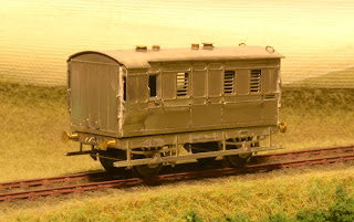
This is the first major item put together from my recent etch. It is modelled on Highland Railway passenger brake van No. 5, as preserved at the SRPS in Bo'ness, and drawn on p.101 of Peter Tatlow's book. Pete Armstrong has also modelled this van in 7mm scale, in his case from the Lochgorm Models kit (see his blog here).

Still missing are vacuum pipes and handwheels, which I will add after painting because I need to make sure that I don't foul the couplings. Glazing will be added simply by slotting into the sides. The white bits are Milliput that I used to fill in some gaps where the parts join together.

Like my previous attempt at a Jones 6-wheel coach, the sides fold up from several layers. This time, I included fold-out footsteps on the inner layer of the end, which fit through slots in the outer layer. I'm very pleased with how it has turned out. The only errors were that I forgot quite a lot of the handrail holes on the inner-most layers. These were easily drilled out, however. Also, I included the handrails on the etch, but these proved too fragile and I replaced them with 0.3mm nickel silver wire.

The photo below shows that there are three main pieces. A 12BA nut is soldered on the inside of the floor (see bottom photo), and this will be used to screw on the chassis. Notice the etched tab on the chassis that locates through a corresponding slot in the floor of the body, to make sure that the two mate together squarely. I'm also showing you the roof here. Following problems trying to bend the full 10 thou thickness for my previous coach, I half-etched much of the material away, just leaving a strip around the edge and a series of longitudinal ribs. This made it much easier to get the curve parallel along the length of the roof, and bending was quite straightforward. I've modelled the lamp-holders in "day time" condition, i.e. no lamps. The covers (and the holes into which the covers fit when lamps are fitted) are made from lengths of brass tube. This was a bit labour intensive so I would quite like to find a quicker method in future.


How exactly I will attach the roof remains to be seen - you can see that it locates on a tab sticking up from the interior spacer. I should probably have included one at the other end. I might even solder in a 12BA nut and use the same fixing screw to attach it, but I don't know whether this will hold the roof down sufficiently around the edges. I may need to glue it. It can't be fixed until after painting because the glazing needs to slot down from the top of the sides - you can just about see the slots in the photo below.

Monday, 31 October 2016

The gatehouse

I've made some progress with the estate gatehouse on Corrieshalloch. This was designed to add a bit of interest to the background where it stretches up above the railway. Rather than model it on one of the real Braemore Estate buildings, I wanted something that was quite small but a little bit distinctive. The model I've made is inspired by the gate lodge at Ardkinglas in Argyll (https://canmore.org.uk/collection/1298177).

This building has a distinctive octagonal footprint which challenged my abilities, particularly on the roof. These photos show the model which is basically a plasticard shell with some reinforcing bits. The walls are covered with cartridge paper to mimic the rendered texture, and the roof uses overlapping strips of slates printed and cut from standard copier paper. I embossed the vertical joints between the tiles first, although I'm not sure they show through much after painting. The small sections of dressed stone (chimney stack and gateposts) are also cartridge paper, with the mortar lines embossed. The chimney pots are some whitemetal castings from my scrap drawer.


The next photo shows the windows, which were the trickiest bit (with a few failed attempts). The glazing bars are just painted on clear plasticard, but to try and get them neat I first scored parallel lines for the straight ones with a knife. I had to wing it for the curved bits. After painting, a cocktail stick was used to scrape off any stray paint up to the hard scribed line. I glued pieces of microstrip around the outside to give a raised frame (made over-thick then sanded down afterwards). The bit of wall here is the second gatepost, on the opposite side to the building.

Here are some pictures of the gatehouse in position on the layout, after some initial coats of paint.  More work will be needed to weather and blend it in with the surrounding scene, but I'm quite happy so far.

You can just about see the gate itself below: this is from a Scale-Link etch and soldered to brass posts which sit in holes in the road. It is yet to be painted.


Friday, 3 June 2016

Perth supermeet

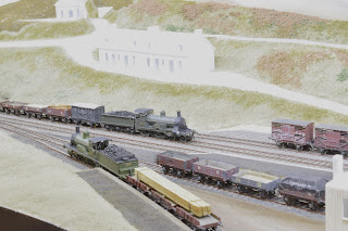
Rather belatedly, here are a selection of photos I took during the layout's appearance at the 2mm Perth supermeet in April. The first two shots show my own stock.

All buildings except for the signal cabin are now plasticard shells, although the station building is missing its roof. I'm trying to progress the layout as a whole, rather than completely finishing one building before starting the next.

The next three shots were staged with some of Alisdair Campbell's fantastic Highland locos and stock (along with my four wagons mixed in...). This is what I am ultimately aiming for, although it will be some time before I manage to build up my own fleet.


Thursday, 2 June 2016

Bank holiday engineering work

The civil engineers had been a tad unhappy with the road overbridge at Corrieshalloch; probably something to do with a number of non-finescale diesel locomotives getting wedged under it. A quick check of the gauge confirmed what I had suspected: when it was glued down it was somehow pushed down too much, and there was insufficient clearance even for scale rolling stock. There was no option but to rip it up again, so on Monday I finally plucked up the courage to do so. (There is definitely something of the "two steps forward, one step back" about my modelling.)

First is a photo with the bridge removed. I took the opportunity to widen the hole in the sky, in an effort to make its edges less prominent. I also painted these black rather than white, although I will probably settle for a shade of grey as melding into the background better. Unfortunately, I had plastered in around where the bridge joined the landscape, so some cutting and chipping away of plaster was necessary.


Next picture shows the modified bridge back in place (though not fixed down yet). It was a simple matter to raise it up a bit, although I will need to touch up the paint on the bottom edges. I took the opportunity to add the other parapet, which I had been too lazy to do at the outset. This will need painting too, and I will also have to touch up the joins in the (polyfilla + PVA) road surface. However, I can now run converted N-gauge locos without them getting stuck!

The backscene at this end of the layout may also receive some more attention - it has been suggested that it would be more aesthetically pleasing if the hills here had a little more height, so I will ponder it. There is also a bit of a join between road and sky that will need disguising better.

Thursday, 24 September 2015

Building bridges

This is the road overbridge for Corrieshalloch. Over recent days, I've been adding the stonework to the previously built styrene shell. It's a mixture of Slater's embossed sheet (intended for 4mm?) and plain white card. Into the latter, I embossed a simple pattern of mortar lines using the blunt end of an old screwdriver. This mixture of materials stemmed from the prototype photo I was copying, which appeared to use a mixture of dressed and rather less dressed stone. I'm hoping that the whole will look ok once painted.

The curved wing walls and elliptical arch were a bit of a pain, but the use of a CAD template was invaluable for the arch.

Saturday, 25 July 2015

How I ballast

I'm rather surprised to see that I haven't updated the blog for several months. One of the main areas of progress since then has been the trackwork. First I glued on Versaline cosmetic chairs to the PCB sleepers (tricky to get them to stay put while the "handles" are cut off, even using Araldite).

Then I painted the track in two stages. First, a coat of Halford's red oxide primer from a spray can. Once this had dried, I used the airbrush to apply a coat formed from various shades of Lifecolor acrylic. For this second coat, I tried to spray mainly from above - by tilting the baseboard on its side - so that the rails would retain some of the rust colour in contrast to the sleepers. The whole lot is now too dark in colour but, since the ballast is also too dark, I will be able to lighten it and create more variation later.

The main point of this post is to show the process I have settled on for deep ballasting. I do a small area at a time, and the task seems to have gone on forever!

1. The area illustrated here is around the crossing of a turnout, so I first mask the crossing and check-rail gaps to try to minimise the amount of ballast ending up in them.
2. I mix up a slightly thinned PVA glue, using car screen wash to dilute it (mainly because I'm already using screen wash later, and have it to hand).
3. Using a paintbrush, I spread this PVA fairly thickly around the area to be ballasted. The idea is to get the lower layers of ballast stuck straight away, rather than laying it completely dry. I find this 
minimises disturbance when wetting it.
4. I apply the ballast to the glued area. I'm using a jar of Carr's "ash ballast" which I acquired some time in the past. It is probably too coarse for ash ballast in 2mm scale, but gives a good representation of stone ballast. I apply it from the folded piece of paper you see here, tapping it to release controlled amounts of ballast. This is then tamped by a combination of fingers, a paintbrush, and finally a cocktail stick to remove errant particles from the sleeper tops. This is the most painstaking task!
 5. The next stage is to thoroughly wet the ballast. I've been using car screen wash which avoids the need to mix up washing-up liquid and water. I'm using this pipette rather than a fine plant mister because I don't have one to hand. I also don't particularly want to have to mask the rest of the layout to prevent it from getting wet. Where possible the drops are placed at the edges of the ballast and allowed to spread in by capillary action. This avoids creating the craters that you get if it is dropped straight onto the ballast from above. Once the screen wash has fully soaked in, I tidy up any stray grains of ballast using a cocktail stick.

6.  The final stage is to add dilute PVA/screen wash to the already wet ballast, again using a pipette. This is something like a 50-50 mix, and can just be dropped on from above once the ballast is already wet. Leave it to dry and hey presto!
Actually this isn't really the end of it, as there is a subsequent painful stage of cleaning the rail tops and removing any stray grains of ballast that have somehow still managed to end up in the wrong place. Once all of this is over, I hope to restore the quality of running that I had at the start. Who said that model railways aren't fun!

Tuesday, 24 March 2015

Seen at Nottingham

Here are a few pictures taken at the Nottingham show last weekend, where Corrieshalloch appeared as a work in progress alongside a sizeable demonstration of 2mm modelling. A first coat of paint on the nascent scenery has made a world of difference!


The next shot is rather grainy - we discovered that those seated at the nearby demonstration table had a nice vantage point:


 Finally a visiting train from points (far) south, courtesy of Pixie:

Saturday, 3 January 2015

Progress on Corrieshalloch

It's about time for an update on the layout. Recently, I've been focusing on basic scenic work: carving the basic contours from polystyrene and coating them with a layer of plaster bandage to give a solid surface.

I've also been working on styrene platforms to replace the rough, temporary foam-board ones that I put in place for the summer exhibitions. I would have used foam-board for the final platforms if it hadn't been the wrong thickness.

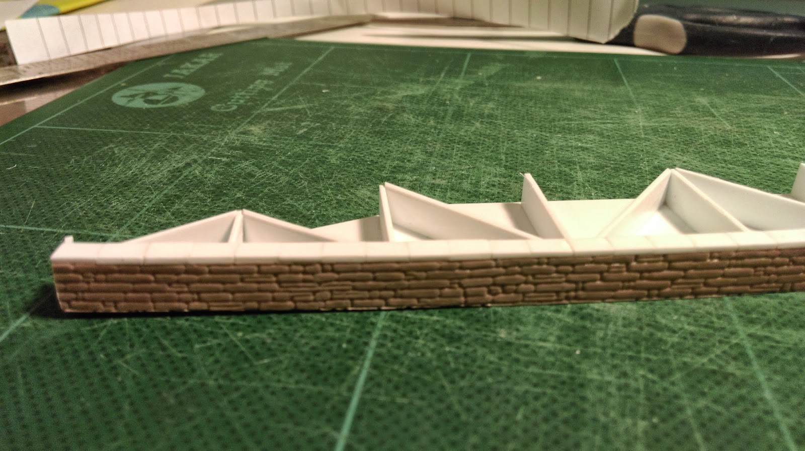
This photo shows how the platforms are constructed from a skeleton of 40 thou styrene sheet, with a facing of Slater's stone sheet. I had this sheet in store, otherwise I would probably have embossed my own stonework in cartridge paper. The coping stones were added individually. After doing this section (the goods yard loading dock), I decided to simply put the coping stones for future sections on top of the platform top surfaces.
Here you see both the front loading dock and down platform in place (temporarily). The platforms are topped with sheets of 30 thou styrene. The dark appearance of the loading dock is an experiment with a piece of wet and dry paper to represent the cinder surface. It looks a bit too neat and tidy so will need some more attention at some point. The rear platform is still in its foam-board state.
The photos below show the up platform, with only the cattle dock outstanding. You also see my mock-up of the exit road bridge. This has a simple styrene underframe (which will be used for the final bridge), and this is temporarily faced with an elevation printed on thin card. I drew it up on QCAD to get the elliptical profile of the arch and wing walls. I'm happy with the mock-up so will now need to recreate the shape in styrene.
Finally, there has been the small matter of taking over editorship of the 2mm Magazine to deal with...

Sunday, 31 August 2014

Lessons from an exhibition


Corrieshalloch made its exhibition debut last weekend at RailexNE in North Shields, albeit as a "work in progress" rather than a finished layout. Overall. I was relieved that it worked pretty well, with the soldering iron having to come out on only two occasions for repairs. A succession of three trains (all of my available locos) supplemented by a class 37 running light engine (courtesy of Mick Simpson) dutifully paraded back and forth. The comments of "oh, look at this one: it's a snowscene" were frequently heard, sometimes intended as a joke but not always. Alisdair Campbell (whose prize-winning Strath made a static cameo appearance) had the inspired idea that we block the line with a snowdrift and suspend operations for an extended lunch break.

One lesson learnt was in the setting up and taking down. It took me a whole hour from close of play to driving away, which seems like a long time given the size of the layout. Although I was working alone, I decided that a lot of time was spent fiddling with nuts, bolts and washers for assembling the legs. As a result, I have now glued washers and nuts to the inside of the legs, and modified the bolts to have a handy wing nut on the outside (photo below). This, coupled with a bit of widening of the holes, should mean that assembly is much quicker and easier in future.

The other major lesson relates to the appearances of the soldering iron alluded to above. Both repairs were to the homemade bolts that connect the fiddle yard turntables. These were originally just soldered to a couple of pcb sleepers glued to the baseboard, but this was far too flimsy to withstand constant use. As pointed out by Mick (after one came off in his hand), heavier engineering is required! So version 2 will see the rails attached to heftier pieces of pcb that are screwed right through the balsa trackbed and into the plywood beneath. Hopefully this will be better. The photo below shows the version 1, as it was at RailexNE.

The turnouts at the entry to the goods yard are also a little bumpy, causing some wagons to couple up again against the operator's will. So another task is to iron out these minor issues with the track.

The good news is that the layout will appear again at Shipley on 20th-21st September, along with the 2mm roadshow, so feel free to pop along and say hello. With any luck, some of the issues above will have been ironed out, and another loco will be in service to boot.