Monday, 8 March 2010

First Steps in DCC

I've finally taken the plunge and purchased an NCE Power Cab system (from Digitrains). This comes with everything you need to get started except a locomotive decoder.

As a first experiment I have converted a brand new Farish Class 24. This is an ideal choice as it is "DCC ready", meaning there is an internal circuit board with standard 6-pin decoder socket, and no need to modify the chassis. The socket comes fitted with a "blanking plug" for ordinary analogue operation.

I believe the idea is to buy a decoder with an integral 6-pin plug and simply plug it in. However, the decoder I bought at the same time as the system was a Digitrax DZ125 without a plug, just with 7 bare wires. These are colour-coded as follows, where the first column gives the numbers of the (labelled) sockets on the loco PCB, according to the NMRA standard:
1 (orange) motor right
2 (gray) motor left
3 (red) right rail
4 (black) left rail
5 (white) front light
6 (yellow) rear light
- (blue) light common
Note that there are 7 wires but only 6 sockets. The blue wire is not needed - the standard is apparently such that if it is not connected then the lights are supplied using the track as the common instead. As I had no plug I unsoldered the socket from the loco and soldered the individual wire ends instead (a bit fiddly and not what the maker intended!). The decoder sits happily where the blanking plug was initially located.

(Note: Sorry there are no photos as my camera is broken).

With some trepidation I assembled a circle of Setrack (the wheels have not been changed yet), put the loco on the rails, connected the Power Cab, and turned it on. It picked up the loco straightaway with the default factory address of "3," and I was able to drive it away with no further ado. One benefit of DCC showed immediately: I could turn the headlights on or off independently of whether the loco was moving (well, it impressed me anyway). When you change the direction on the controller, the lights change colour too.

I then followed the "Getting started" instructions in the Power Cab manual to easily program a long address for the Class 24. In the default state the operation was not smooth, increasing in 28 discrete steps from standstill to ridiculously fast. I expected it to be a lot of work to remedy this, but in fact it was simple. Following the instructions in the manual again (at least to begin with), I rapidly obtained fantastic running by programming the Class 24's decoder through the following procedure:

(1) Change the start voltage - configuration variable (CV) 2: I tried increasing this in single steps (these variables take values from 1 t0 255) until the loco just starts moving on speed step 1 (initially there was not enough voltage until speed step 2).
(2) Change the maximum voltage CV5: I lowered this to get a more reasonable top speed.
(3) Change the mid speed voltage CV6: I put this mid-way between my new values for CV2 and CV5 (not sure if it was necessary to set this independently).

With these settings the loco was able to run at a reasonable range of speeds, from an incredibly slow crawl to a reasonable pace. I then got adventurous and fiddled with CV3 (acceleration rate) and CV4 (deceleration). By default these are set to 0 so the loco moves instantly at the new speed, creating an undesirable jerky effect. By setting a non-zero acceleration I found that the loco could move very smoothly from one speed to the next, despite the fact that there are only 28 discrete speed steps on the controller. Nice. I opted for only a small deceleration rate so that the braking is also smooth, but is quick enough that I can control where the loco stops.

That concludes my DCC experiences so far. Unfortunately I only have one "chipped" loco as yet, so I can't experiment with controlling multiple locos at once. Although, on Inverneuk this will be something of a challenge. Time to order a decoder for the 08 I think...

Saturday, 6 March 2010

Seen at Model Rail Scotland

I spent an enjoyable day at the SECC last weekend including a stint on the 2mm stand with Inverneuk.

Andrew Peggie managed to film Mick Simpson's Class 25 at work shunting the yard...


Saturday, 28 November 2009

The Warehouse

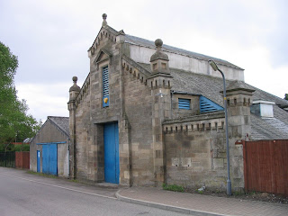
An interesting building on Inverneuk is a low-relief version of this warehouse at Tain:
I took this photo while passing through on a (road) trip up North in June 2008. A couple of older views may be found at http://rniescottishailwayrchive.fotopic.net/p25206879.html. In particular, I have included the hoist on the front of the building that is no longer present, and have omitted the burglar alarm.

I began by preparing an approximate scale drawing (on the computer, based on the photos). This was printed out and mounted on cardboard as a mock-up, as featured in this shot of the embryonic scenery:
Construction of the basic superstructure was in styrene sheet. The stonework was laboriously embossed in cartridge paper which was then glued over the plastic shell. The ornamental tops to the walls, including the round finials, were scuplted from Milliput. The triangular sections were formed by running along a plastic scraper with a cut-out of the desired cross-section, although this required just the right "wetness" of the Milliput. The hoist was knocked up from scrap brass strip and bullhead rail.
Unfortunately this building (like the goods shed) is too tall to fit in the box file, so I made the upper section removable:
Here is the finished building in place, painted in acrylics. The surrounding scenery still needs development.

Monday, 14 September 2009

08 Update

I've made some progress: constructing the outside frames and, most recently, fitting the coupling rods. The trickiest part was soldering the cranks squarely to the extended axles. When quartering I had to make more adjustments to deal with crankpins that weren't parallel to the axles than I did to get the angles of each wheel right.

I'm still not totally convinced that the chassis rolls down the tilted test track as smoothly with coupling rods as without, but it's close. I still need to attach the motor and see how it runs. Luckily the wheels are just held in the muffs by friction so are still adjustable. I haven't decided yet whether to glue them or not, but if I opt for glueing I want to check more carefully with a back-to-back gauge first (which I need to obtain...).

Saturday, 13 June 2009

BR Blue CCT

I've been working on the Chris Higgs BR CCT. Here is a quick preview of the model with base coat of paint, showing the home-produced transfers. Weathering, glazing, and handrail details are still to be done.

Monday, 25 May 2009

08 Shunter Progress

In the last month or so I've begun construction of the 2mm Scale Association kit for the BR Class 08 shunter. I've found Graham Ross' blog about the construction of this kit very helpful.

Here is an early view of the frames, with bearings and PCB spacers attached. You can also make out the phosphor-bronze springs, following the method of Mick Simpson. The frames have half-etched holes intended for these. As recommended, the springs came from straightening out Farish N-gauge coupling springs. With this method you also have to shorten the muffs on the axles, which I did by a combination of stanley knife and filing.

This view was taken this morning, showing the chassis with all wheels and gears fitted for the first time. I opened out the muffs on the axles with a 1.5mm drill, so that the wheels are an easy push fit. Hence I will be able to correct the misaligned balance weight on the right-hand wheel! I think when I am happy with the drive I will have to glue the wheels in, by means of the perpendicular hole drilled in the centre of each muff. Unfortunately one of the large balance weights disappeared in between cleaning up and glueing in place, so I had to make a replacement by carefully filing a piece of spare nickel-silver fret.


Finally here is a video of the first "test run" with the motor attached. There is still work to be done in getting it running smoothly. Before this video was taken I found that one of the spur gears was locking, which I seem to have cured by opening out its bearing hole slightly (perhaps it was a result of the axle bearings being opened out to 1.6mm for the springing system?).

Sunday, 3 May 2009

Trackwork

As I haven't posted anything about my Inverneuk layout for some time, here is a photo sequence illustrating the method used for trackbuilding.

I used plain rail and PCB sleepers, following closely the excellent instructions in the Beginner's Guide. Building turnouts turned out (sorry) to be much easier than anticipated, having been one of my two main concerns about working in 2mm scale (the other is building working locos, of which more anon). Although I used the standard jig for building plain track, I didn't use a jig for the turnouts, simply building directly on to an Association plan. For simplicity I decided not to design my own tighter turnouts. No chair-plates were used (Inverneuk is a light yard anyway). Two further points. Firstly, I find that running a file along the outsides of the chairs after construction gives a more uniform appearance. Secondly, you can see the gaps filed in the sleepers: these were filled with milliput after construction.

In a departure from more normal practice, the next thing I did was not to fix down the track. Instead I constructed it in several sections, and, while they were still loose, soldered dropper wires to each length of rail. Corresponding holes were drilled in the baseboard. Away from the layout I then sprayed the track sections with primer and brush painted the sleepers and rails with acrylics. However, I'm not convinced acrylics were the best paint for this as they tend to peel off and have had to be re-touched since. The idea of painting the track before fixing follows an article by Bill Blackburn in the 2mm Magazine where he describes how he lays and ballasts the track at the same time.

Here we see a section of track in the process of being layed, alongside a completed section. Pins are prepared to hold it in position, then PVA glue is spread in quite a thick layer underneath, before fixing down the track. At the same time dropper wires are fed through their holes. Then, while the glue is still wet, ballast is sifted into place. I found it advantageous to tamp the ballast at this stage too. After allowing the glue to set the layout was shaken upside down to remove loose grains, and the ballast was touched up where required. At the same time stray grains that had stuck to the sides of the rails were removed.

The choice of ballast material resulted from some experiments. I settled for a mixture of Carr's ash ballast and sand from the local beach. Here is the real thing, on the Kyle line.

And here is the finished track!

P.S. Inverneuk now appears in print (2mm Magazine for April/May 2009).